")
Sap Flow Correction Parameters Explained.
The raw temperature data collected from an Implexx Sap Flow Sensor needs to be corrected for accurate sap flux density and total sap flow measurements. The raw temperature data and correction parameters are inputs in the IMPLEXX-SF Sap Flow Excel Workbook which then converts these values into sap flux density and total sap flow.
This article defines the correction parameters and how they can be measured in the field. The correction parameters are:
- Wound diameter;
- Sapwood wet weight;
- Sapwood dry weight;
- Sapwood wet volume;
- Dry density of sapwood (DDW);
- Stem or trunk diameter (TDD);
- Bark depth (BDD); and
- Sapwood depth.
The following parameters are required to correct for probe misalignment:
- Outer downstream distance;
- Inner downstream distance;
- Outer upstream distance; and
- Inner upstream distance.
Download a PDF of sap flow sensor correction factors.
Wound diameter.
 Equipment Required:
- Calipers
- Dissecting blade
- Hand lens or dissecting microscope
Wounding is an inevitable consequence of drilling into the plant and inserting the sensor probes. For accurate sap flow data, it is critical that wounding is measured and corrected for in converting heat pulse velocity into sap flux density and sap flow.
The wound should be visually observable once the sensor probes have been carefully removed from the plant. You may need to scrape away, or remove, the bark with a dissecting blade to visually see the wound on the sapwood.
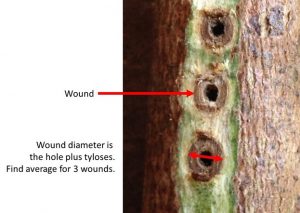
The wound is the hole where the sensor is inserted into the plant plus a ring, or donut, shape surrounding the hole. This is tyloses – or cell death to prevent infections from entering the plant.
Measure the wound diameter with a set of callipers. Measure the average of the three wounds from the three sensor probes.
Wound diameter value should range between 0.17 and 0.3 cm (centimetres).
Sapwood wet and dry weight and wet volume.
 Equipment Required:
- Increment borer
- Secateurs
- Dissecting blade
- Calipers
- 3 or 4 decimal point weigh scale
- Drying oven
The sapwood fresh volume, weight and oven dry weight is measured to determine the wood bulk density and gravimetric moisture content of sapwood.
A sample of sapwood must be collected from your measured plant. For large trees, a sample can be collected using an increment borer. For small stems, a sample can be collected using secateurs and a dissecting blade.
It is important that only sapwood is sampled. Do not measure bark and/or heartwood.
Sapwood wet weight.
 Immediately following the collection of the sapwood sample, it is important that the weight of the sample is measured.
Ideally, the sample should be weighed immediately. However, in the field this may not be possible. Therefore, wrap the sample in parafilm or other material to prevent desiccation. Place the sample in a zip lock bag and into an Esky or ice container. You need to ensure that moisture loss is minimised.
Sapwood wet volume.
Immediately following measuring sapwood fresh weight, it is important that the shape, or volume, is measured.
With a sample from an increment borer, you can carefully cut the ends of the sapwood core to create a cylindrical shape. With a set of callipers, measure the height and diameter of the cylinder and calculate volume.
With a sample from a small stem or wood section, it may be possible to cut the sample into a cube, cuboid or cylinder to measure the volume.
Often, the shape will be irregular. For these samples, the volume can be determined following Archimedes’ principle.
Sapwood oven dry weight.
Place the sample in a drying oven at a temperature of 70 °C to remove all moisture from the sample. Depending on the moisture content of the sample, it may take several hours or a couple of days to remove all moisture.
Every few hours, remove the sample from the drying oven and re-weigh. Once the weight is no longer decreasing, then all moisture has been dried from the sample. This is the oven dry weight.

Dry density of sapwood (DDW).
DDW is calculated by dividing sapwood dry weight by sapwood wet volume. DDW is also denoted as pd.
DDW or ρd = Sapwood dry weight (grams) / Sapwood wet volume (cm3)
The IMPLEXX-SF Sap Flow Excel Workbook requires DDW to be entered with the units of g/cm3. Values of DDW range between 0.250 and 1.250 g/cm3. Typically, for most commercial horticultural crops, DDW ranges between 0.400 and 0.800 g/cm3.
Implexx Sense has a database of DDW values for a large number of species. Contact the scientists at Implexx Sense to see if your species is listed in the database.
Stem or trunk diameter (TDD), bark depth (BDD) and sapwood depth.
 Equipment Required:
- Diameter tape
- Callipers
- Increment borer
It is critical to measure the size of the plant to convert sap flux density into volumetric, or whole-plant, sap flow.
Measure the diameter of the plant where the sap flow sensor was installed with either a diameter tape for large trees or callipers for small stems.
Measure the bark depth, or radius, of your plant.
Measure the sapwood radius, or depth, at the location where the sap flow sensor was installed. Ideally, a cut stem is the most accurate approach to measure sapwood radius. For small stems a pair of secateurs can cut the stem. For large trees a chainsaw, operated by a qualified technician, may be required. Only operate a chainsaw under appropriate supervision and training.
Where it is not possible to cut a large tree, an increment borer can be used to measure sapwood radius. With the increment borer, sample to at least halfway into the tree. Remove the core and measure the sapwood length.
Note that sapwood depth may be irregular around the circumference of the tree. You may need to measure at several circumferential locations to better understand the distribution of sapwood.
Probe misalignment.
What is probe misalignment?
Accurate measurements of sap flow and stem water content are highly dependent on knowing the exact distance between the heater probe and the temperature sensors. By design, the temperature sensors are 0.6 centimetres (cm) distance (i.e. x = 0.6) on the Implexx Sap Flow Sensor. In practice, the exact distance is almost never 0.6 cm. When the distance is not 0.6 cm, this is known as probe misalignment. For extremely precise measurements of sap flow and stem water content, it is important to correct for probe misalignment.
In our experience, the distance between temperature sensors and the heater ranges between 0.5 and 0.7 cm. Most commonly, it is within ±0.05 cm – that is only half a millimetre offset in the correct placement of the probe which is only a small distance. Regardless, where precision measurements of sap flow and stem water content are required this offset must be considered.
Note that the probe misalignment in the following schematic has been over-emphasised. The schematic is a representation of various probe misalignment scenarios.

What causes probe misalignment?

Probe misalignment can occur even when extreme care is taken with drilling and the installation process. Grapevines, such as seen here, can be difficult as well as installing a sensor where the trunk is at an unusual angle.
During the installation process, it is common for the temperature and/or heater probes to be unintentionally installed at a slight angle relative to the other. Despite drill guides, it is almost impossible to install probes exactly parallel. Unfortunately, we are not machines or robots and it is difficult for any user to precisely install every probe.
Probe misalignment is most common when an installation is rushed. It is extremely important to slow down and carefully install the probes in the stem. Probe misalignment is also common when the installer is tired and is common towards the end of a long day in the field.
Even when extreme care is taken during the drilling and the installation of probes, it is still possible for the probes to be misaligned because of xylem anatomy. The assumption is that the xylem conduits, such as tracheids and vessel elements, are perfectly perpendicular to the probes of the sap flow sensor. However, it is impossible to know prior to an installation the distribution and arrangement of xylem elements. Therefore, even when the probes of the sap flow sensor are perfectly parallel, the tracheids and vessel elements may be offset on a slight angle which subsequently alters the distance between the heater and temperature sensors. This problem is commonly observed in woody vines, such as grapevines, where xylem anatomy may be tortuous. It may also occur if a sensor is installed near an old branch, or bole, or where a trunk or stem is on an unusual angle.
It is, therefore, difficult to always install every sap flow sensor perfectly. A correction to the data is inevitable and various methods of correction are outlined below.
How do I know if my probes are misaligned?

An example seven-day data set showing probe misalignment. In this case, night-time values are approximately -0.15 cm/hr when the value should be 0 cm/hr. The difference is due to probe misalignment.
The best method to determine probe misalignment is to examine heat velocity in the outer and inner measurement positions. Night-time heat velocity, when relative humidity is ~100 %, and soil moisture is saturated or at field capacity, should be 0 cm/hr. Under these saturated conditions, there is no energy driving sap flow in xylem which is why heat velocity should be zero. If heat velocity is not zero, then it is likely there is probe misalignment.
Probe misalignment is most obvious when there are several nights of observations. For example, the figure to the right shows seven nights of heat velocity data. The solid red line along the x-axis is where heat velocity equals 0 cm/hr. However, the blue line, which is observed heat velocity, is negative during the night. This is an indication of probe misalignment. When night-time data, which should be zero, is either negative or positive then this is probe misalignment.
Importantly, it must be a flat line at night. This is best demonstrated on Night 5 in the figure above where heat velocity is a flat line all night. This is clearly a period of zero sap flow when values should be 0 cm/hr. Yet, the heat velocity on Night 5 is approximately -0.15 cm/hr indicating probe misalignment.